Solar Powered Antenna Tuner
Let the sun tune your antenna! Well not really, but it can recharge your battery in your remote tuner.
Background: When I received my LDG Z-11 Pro-II tuner ( https://ldgelectronics.com/wp-content/uploads/2018/11/Z-11ProIIManual.pdf ) the manufacturer states that it could be powered from just AA-sized batteries. At the minimum, 6 batteries were recommended. Hum, the 9 Volt source could be mounted inside the tuner or it could remain outside the chassis. So, I thought, why not just power the tuner from an external battery that could be located at the base of my antenna. The reasoning is the tuner would tune the feed line connecting it to the height of the antenna (about 35 feet in my case) and present a 50 ohm load impedance to the coaxial cable that runs to my ham shack, about 85 feet away. This way, the VSWR on the main length of coax is 1:1 or at worse about 1.5:1 and this minimized the transmission line loss back to the station rig.
Using a remote tuner is nothing new to me. I have been using an LDG RT-11 tuner for about 5 years at the base of my dipole support tree. The RT-11 is a little long in the tooth and has been discontinued by LDG. So what to do for an upgrade? Why not use battery power at the tuner and let the sun keep them charged? Thus, the birth of the Solar Powered Antenna Tuner!
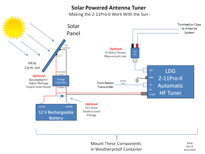
Block Diagram: A simplified diagram for the Solar Power Antenna Tuner is shown below. I have selected a minimal power solar cell because the tuner only requires a burst of current whenever it is being tuned and the batteries can handle this type of load. An optional 4 to 1 (4:1) balun is also shown connected to the output of the tuner. This is needed if you want to increase the impedance matching range or to provide a balanced connection to a balanced transmission line.
EDM
Unit: My
engineering development model (EDM) uses a solar cell array shown at the left. It provides plenty
of charging current to the internally mounted, sealed lead acid, 12 V battery.
Mine is manufactured by Uni-Solar,
Model USF-11, 10 W flexible panel that can provide up to 620 mA on a direct
sunlit day. On a cloudy day, the current is much less than this. Clearly an overkill for this project but does provide data as part
of my EDM study. When larger solar arrays are used, the open circuit voltage can
rise to 21 V if a battery is not connected. Also, you don't want to overcharge a
small battery. This is where the optional charge controller
and 15 V zener diode helps limit the charge and voltage. The charge controller
is an older, 10 Amp model from IPC Global. It limits the
charge current to a maximum of 7 A, well beyond the capability of the solar
array. But it also limits the charge current until the batteries reach their
full potential voltage. But, without a batter "load" the open voltage can be as
high as the solar array allows, typically 18 to 21 volts. This beyond the
voltage range of the Z-11 Pro-II so an optional zener diode (1N5352, 15V, 5W,
https://www.digikey.com ) is shown in the
figure. This will keep the voltage from spiking above 15 volts if the battery
were to become disconnected while the solar charger is connected.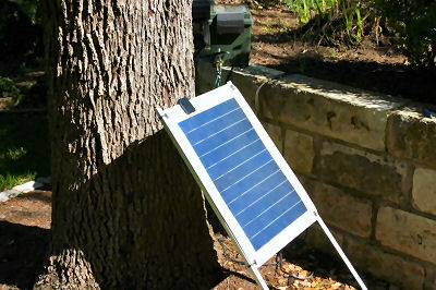
An appropriate and smaller solar cell array is one
that is used to charge deer feeders. The one shown is from Native Outdoors
website,
https://www.nativeoutdoors.com , P/N SP60-12V. It has an IPC rating of 70 mA, maximum. 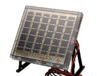
Native Outdoors
P/N SP60-12V
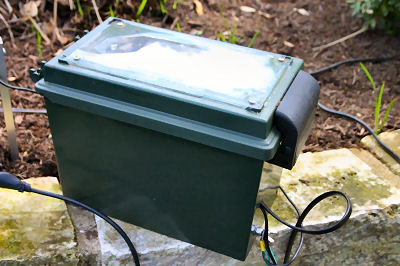
Caption: Solar Panel Next to the Weather Proofed Containers
The solar array should be tilted to the mid-day sun so it directly faces it. This could be sometime between 12 p.m. and 2 p.m. depending your geographic location and whether you observe daylight savings time. Since afternoons are normally more sunny than mornings, I prefer to use 2 p.m. as the time to establish maximum sun exposure.
Mechanical: I chose to mount the parts in a plastic, weather proofed utility box that are inexpensive and available at a local sporting goods store. No doubt, these can be found at a number of outlets or on the web. The green colored box was the case of choice for the RT-11 remote tuner so it was a snap to convert it over to its newest sibling, the Z-11 Pro-II. The rechargeable battery is a small sealed lead acid (SLA) 12 volt battery but the current requirements are less than 300 mA for a few seconds max. Once the tuner determines the frequency of the RF signal being transmitted, it stores the tuner settings in its non-volatile memory for use in future tuning events.
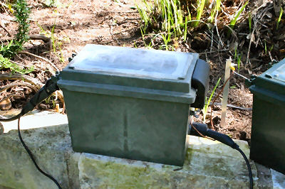
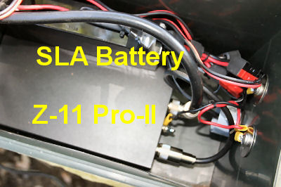
Caption: Weather Proofed Containers, exterior and interior. The interior view reveals the Z-11 Pro-II tuner on edge and the 12 V sealed lead acid (SLA) battery on it's side. PVC pipe fittings are used for cable ingress and egress. Heat shrunk tubing with tie wraps are used to keep the water and bugs out of the container.
I will eventually include some photographs and other interesting power measurements as more time is spent using the tuner. This is an automatic tuner, so it will initiate its tuning cycle whenever the VSWR is greater than a preset limit, such as 2:1 or higher. All of this is discussed in the excellent LDG tuner manual available on-line as a PDF download.
Training the Tuner: My initial usage of the tuner was on 20 meters. I reduced my power to around 10 W and transmitted a continuous wave (CW) carrier. By watching my VSWR meter located in the ham shack, I could immediately see the tuner begin hunting for a low VSWR. Sure enough, after about 3 to 5 seconds, the VSWR was tamed. It measured a cool 1:1 in the shack. Next I moved up the band to about 14.250 MHz. Again, using a small CW carrier, the tuner began searching, hunting, stabilizing, and finding a 1:1 match. What is happening is each time the tuner reaches success, it stores the measured frequency (it does have a frequency counter built in) and tuner L-C switch settings into non-volatile memory. Of course wherever I was testing and training, I transmitted my call for ID as required. The cool thing is whenever I went back to a previous spot, the tuner knew where to tune without hardly any searching; clearly reaching match in less than 1 second. So that is how I trained the tuner on 20 meters. I next went to all other ham bands, from 80 meters through 10 meters, and was able to reach a match at all frequencies. Very cool. Now, I can just pop down to a band and frequency, and bam, the tuner finds a good match. If by chance the frequency does not match well, I can watch the in-shack VSWR meter as it quickly searches and finds a good match.
Tune 160 Meters: For those that noticed there are 2 weather proofed containers, the second one is home to a loading coil useful for taming my dipole and twinlead on 160 M. The twin lead is shorted together to form a single electrical connection to the top dipole that becomes a capacitive hat. By adding the coil, with an inductance up to 32 mH, I can use the tuner to work 160 and 80 meters. I plan to add a DPDT relay so I can select the configuration from the shack whenever I want. For now, I have to open the box and move some jumpers on the terminal strip that is clearly visible in the photo.
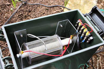
Caption: Photos of my remote load coil box. Same type of container as the tuner but this box contains a loading coil with taps to tune to 160 meters.